🏁 Speedway Motors Tubular Control Arm & Sway Bar Kit – 1955-57 Chevy Bel Air & Nomad
55-57 Chevy Bel Air, 55-57 Chevy Nomad, Powder Coated
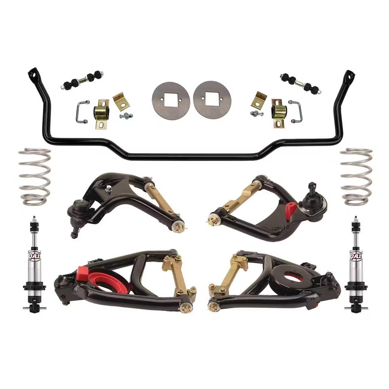
This Speedway Motors Tubular Control Arm & Sway Bar Kit is a direct bolt-on upgrade for 1955-57 Chevy Bel Air & Nomad models. It replaces the factory stamped steel control arms & sway bar with heavy-duty tubular components for increased strength, improved alignment adjustability, and modern handling.
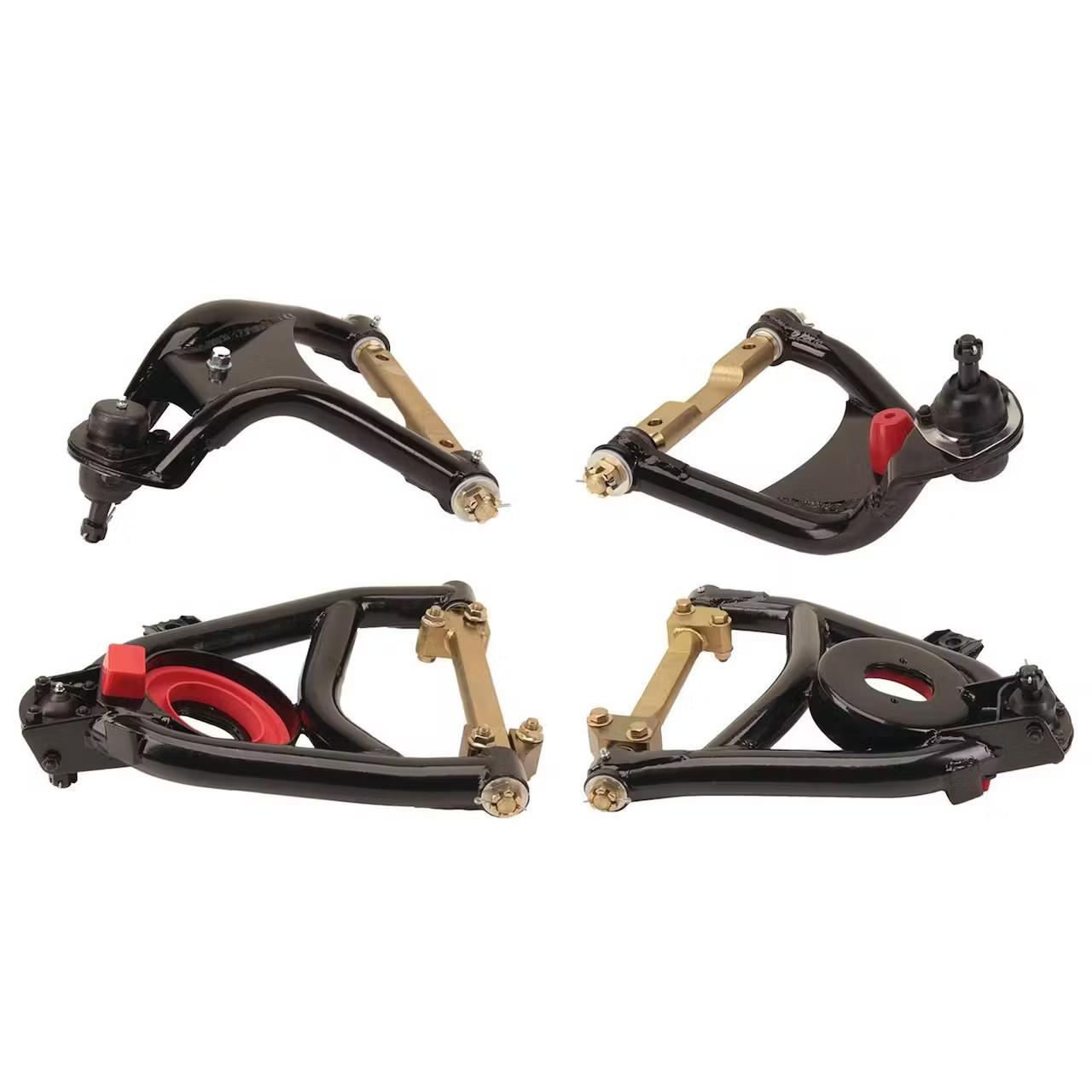
🏁 Tubular Upper & Lower Control Arms – Improve caster, camber, and overall steering geometry
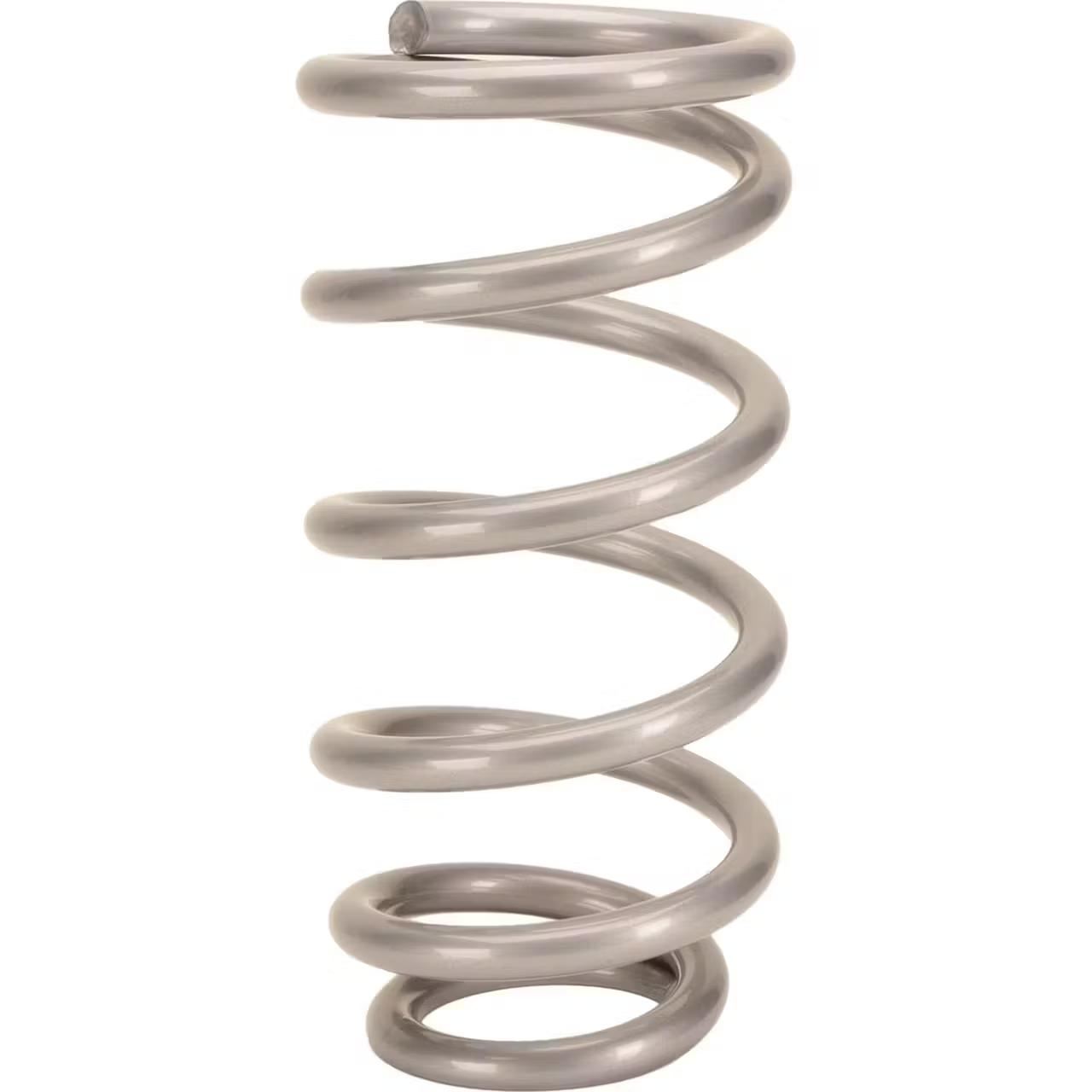
🏁 450 lb. Spring Rate Coilovers – Performance springs for street & track driving
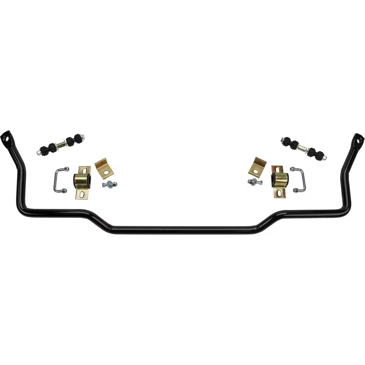
🏁 1” Solid Steel Sway Bar – Reduces body roll for better handling & cornering stability
🏁 OEM-Style Ball Joints – Greaseable for long life & easy maintenance
🏁 Durable Black Powder Coat Finish – Rust-resistant & long-lasting durability
🏁 100% Bolt-On Installation – No welding or modifications required!
Perfect for restorations, performance street cars, and Pro Touring builds, this high-quality control arm & sway bar kit will modernize your Tri-Five Chevy’s front suspension for a better ride & improved handling!
🔹 Why Choose This Speedway Motors Control Arm & Sway Bar Kit?
✅ Better Handling & Stability – Reduce body roll & improve responsiveness
✅ Durable & Strong Tubular Steel Construction – More rigid than stock components
✅ Optimized Caster for High-Speed Stability – Ensures better cornering & steering feel
✅ Coilover Compatibility – Works with stock or aftermarket coilovers for adjustable ride height
✅ Bolt-On Fitment – No Modifications Needed!
🔹 Technical Specifications
⚙️ Control Arm & Sway Bar Details
| Feature | Details |
|---|---|
| Brand | Speedway Motors |
| Vehicle Fitment | 1955-57 Chevy Bel Air & Nomad |
| Front Suspension Type | IFS (Independent Front Suspension) |
| Control Arm Style | Tubular |
| Spring Rate | 450 lbs. |
| Shock Adjustability | Single Adjustable |
| Sway Bar Diameter | 1″ |
| Coilover Compatibility | Yes |
| Finish | Black Powder Coated |
| Bolt-On Installation | Yes |
🔹 What’s Included in the Kit?
✔ Tubular Upper & Lower Control Arms (Stronger than stock, with greaseable ball joints)
✔ 1” Solid Steel Sway Bar (Reduces body roll for better cornering)
✔ 450 lb. Coilover Springs (Optimized ride quality & performance)
✔ All Necessary Hardware for Installation
🚨 Note: Coilover shocks sold separately
🔹 Recommended Upgrades & Add-Ons
🛠 Suspension & Handling Enhancements
- Coilover Shock Kit – For adjustable ride height & improved performance
- Performance Sway Bars (Front & Rear) – Reduce body roll & improve handling
- Steering Box Upgrade – For more precise steering response
🏎️ Braking & Performance Enhancements
- Power Disc Brake Conversion Kit – Essential for modern braking performance
- Stainless Steel Brake Lines – Improves pedal feel & braking response
- Performance Brake Pads – Enhanced stopping power for street & track use
❓ Frequently Asked Questions (FAQ)
🔹 Will this fit my car?
- Yes! This kit is designed specifically for 1955-57 Chevy Bel Air & Nomad models.
🔹 Do I need to modify my frame or suspension?
- No, this is a direct bolt-on upgrade with no welding required.
🔹 What type of shocks can I use?
- This kit is compatible with stock-style shocks or aftermarket coilovers.
🔹 How does this improve handling?
- Stronger control arms, better alignment geometry, and a performance sway bar provide more stability, better cornering, and improved steering response.
🔹 Can I use this on a Pro Touring or Resto-Mod build?
- Absolutely! This kit is perfect for high-performance street cars & Pro Touring setups.
🔥 Call to Action – Upgrade Your 1955-57 Chevy Today!
Transform your Tri-Five Chevy’s suspension with this Speedway Motors Tubular Control Arm & Sway Bar Kit! Enjoy better handling, improved steering, and a stronger front end with an easy bolt-on installation.
🛒 Order now & give your classic Chevy the suspension it deserves! 🚀
Guides & Documents
Prepping Control Arms for Coil-Overs – 1967 Chevelle
As promised, this article dovetails off the end of the control arm article. Since these two projects were done concurrently, now seems like a good time to cover the process of prepping these arms for use with coil-overs.
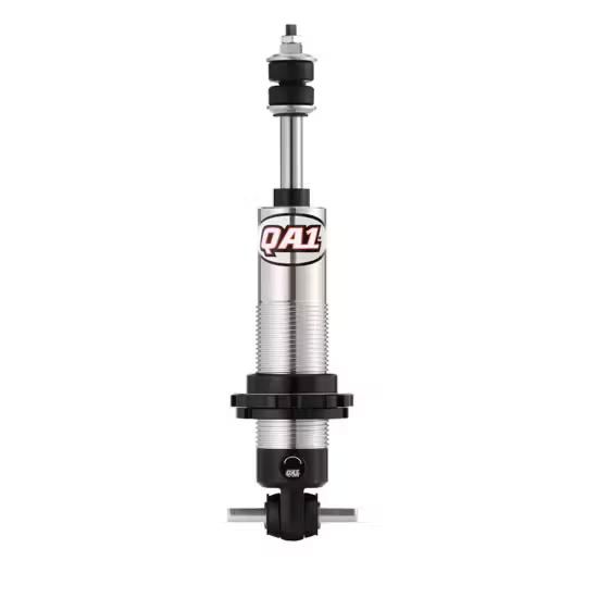
Normally the front shock absorber mounts from below the control arm with bolts that tread into a speed nut or welded nut (in this case) on the lower control arm. When you change that shock absorbers work load to also include supporting the weight of the vehicle, which requires that you place that load on top of the control arm in order for the load to transfer to the arm via direct contact rather than through the tensile load on the bolts. Below, I’ll detail the steps that I took to ensure this conversion would perform and last.

I drilled out the old nuts as best as I could with a step drill, ensuring that I didn’t open up the holes in the control arm any larger than the newly required 3/8”. Then I was able to break away most of the remaining nuts with lineman’s pliers to leave just the welds to be ground. I ground and smoothed away the welds with a cutoff wheel on my angle grinder.

Since the new hardware supplied with the QA1 coilovers upgraded these fasteners to 3/8” fine thread, I drilled those holes to the new dimension after grinding was complete.

This led me to a new concern. The way that the “top hat” for the lower shock mount is designed leaves a large, unsupported area directly under where the cross-bar of the coil-over will rest. Given the punishment that a big block, plus air conditioning, plus aggressive driving will give, I decided to try and come up with a way to beef this area up.

What I came up with is this. Now sold under part #910-3610, this reinforcement plate sandwiches between the coil-over lower mount and the mounting pad on the arm. This plate takes the load and spreads it across the entire top-hat area and being over-sized also provides a block-off plate for the now unused coil spring pocket. Which may otherwise collect debris.
With prototype parts in hand I assembled the coil-overs per the instructions provided by QA1. I opted to add the Torrington bearing kit as well to aid in future ride height adjustments.


During installation I noted that the increased thickness of the plates caused the bolts not to protrude far enough into the nylock nuts to actually engage the locking ring. I chose to source new bolts that are .25” longer to ensure good engagement.
Something else that I’ve found essential to happy life with coil-overs, is the liberal application of anti-seize to the aluminum threads on the body of the shock. This will pay dividends down the road when you want to make adjustments to your setup.
All in all, this was a very productive upgrade and went a long way toward my goal of getting the car back down on the ground and on four wheels again.




Reviews
There are no reviews yet.